|
|
|||||||||||||||||||||||||||||||||||||||||||||||||||||||||||||||||
Complications of Locked Volar PlatesDavid L. Nelson, MD
|
|||||||||||||||||||||||||||||||||||||||||||||||||||||||||||||||||
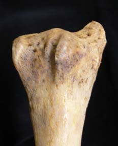
| To summarize: in locked volar plating for DRF’s, in terms of “bicortical purchase”, the “proximal cortex” is the plate and the “distal cortex” is the subchondral bone. There is (1) no need to engage the dorsal cortex, (2) the tendons and posterior interosseous nerve are in close apposition to the dorsal cortex (<1 mm), (3) it is difficult to determine the precise location of the dorsal cortex and the tendons or nerve in relationship to the tip of the screws, and (4) slight pastpointing (~ 1 mm) can lead to tendon or nerve injury. It is recommended to have the screw tips 2 to 4 mm short of the dorsal cortex on the lateral xray. |
![]()
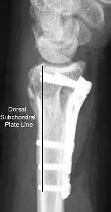
(2) Placement of the Distal Screws into the Radiocarpal Joint
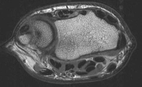
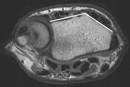
The distal screws should support the subchondral bone, requiring the placement of the plate as distally as possible, and yet not so far as to place the screws into the joint. Is the plate distal enough, with the subchondral bone optimally supported? Is the plate too distal, with a screw into the joint? This is the intraoperative quandry we face each time we place a locked volar plate. Intraoperative fluoroscopy is routinely used to assess the location of the screws. In conventional fracture management, true PA and lateral xrays have normally been obtained. These views have been adequate prior to the advent of locked volar plating. However, the need for screw placement immediately under the subchondral bone, yet not into the joint, has led to a need for a level of precision not previously required (on the order of a mm or two), and true lateral radiography has been found to frequently be misleading. How can we obtain the accuracy the new technique demands? The anatomy of the distal radius provides the answer.
| Practical tip: To determine whether or not a screw will be into the joint, prior to drilling, place a K-wire though the drill guide locked into the screw hole in the plate. Remove the guide and plate, leaving the K-wire in place. Obtain a fluoroscopic view of the K-wire end-on. This view will precisely determine where the screw will be once it is placed. |
The Lateral Facet View
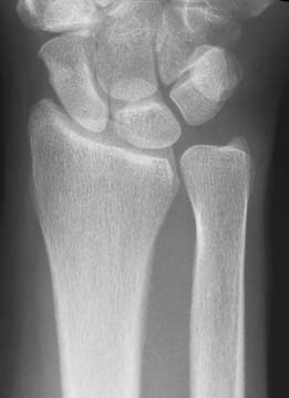
Figure 13
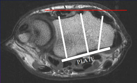
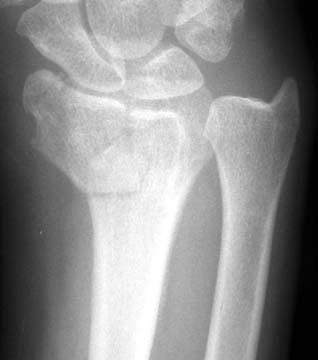
Figure 13 is the PA view of a normal distal radius (although there is an ulnar plus variant). The articular surface is curved, but if it is approximated as a straight line, it is tilted approximately 21°. The true lateral of the radius, therefore, does not profile the scaphoid and lunate facets, but views them on at a 21° angle. If the forearm is tilted by approximately 21°, the facets can be seen in true lateral profile, and the view is called the lateral facet view.
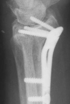 Figure 14 True lateral view |
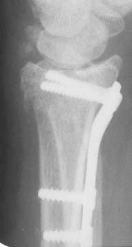 Figure 15 Facet lateral view |
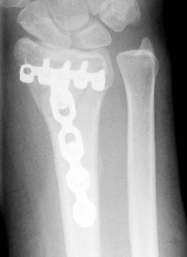
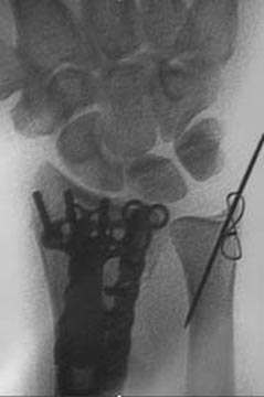
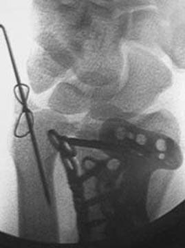
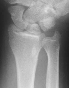
Figure 14 is a true lateral, appearing to show penetration of the joint space by several screws, and flagrant violation of the joint space by the radial styloid screw. However, the screw position resolves with a facet lateral view (Figure 15), with the majority of the screws nicely supporting the subchondral bone.
The PA Facet View
The distal articular surface of the radius has an 11 degree volar tilt. A true PA view of the radius, therefore, will give a tangential view of the scaphoid and lunate facets. A true PA of the facets can only be seen with an 11 degree tilt of the radius. This is called the PA facet view.
Many true PA views will seem to show the screw tips extending into the joint. A facet PA (Figure 16) will show that their true location. In practice, both the facet PA and the facet lateral are used.
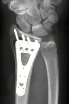
Figure 14
PA facet view
| To summarize: volar plating of the distal radius requires a precision in screw placement that is unprecedented. Standard views will not be sufficiently accurate. Facet PA and facet lateral views are required, both in the OR and in the office. |
| Practical tip: In the office, if the wrist is placed on a full roll of cast padding with the elbow left on the cassette, an excellent lateral facet view will be obtained. A similar PA facet view can be obtained by elevating the wrist on a full roll of cast padding with the elbow left on the cassette. |
| Practical tip: When using fluoroscopy in the operating room, do not tilt the patient’s arm, as in the above Practical tip. Instead, tilt the fluoroscopy arm for both lateral facet views and PA facet views. Rotating the patient’s wrist while the C-arm is tilted will then also provide excellent oblique facet views. |
| Practical tip: Do not completely tighten the rotation clamps on the mini-C arm, but keep them just loose enough so that you can tilt the arm when you need to. The author finds it is fast and easy to control the angle of the mini-C arm in order to get the precise angulation required, to place one hand on the upper portion of the arm and one toe hooked on the lower portion of the arm. |
![]()
(3) Irritation or Rupture of Volar Tendons due to Prominent Plates or Backing Out of Distal Screws
Some of the early locked volar plates and some of the first versions of current plates were more prominent than some of the other current generation plates. The Synthes volar 2.4/2.7 distal radius plate, colloquially called the “volar Π plate” , was a great innovation, but had the disadvantages of both raised margins around the screw holes and sharp edges because the width needed to be trimmed to size. When selecting a locked volar plate, be sure that it is properly pre-contoured, low profile, and smooth on its distal margin.
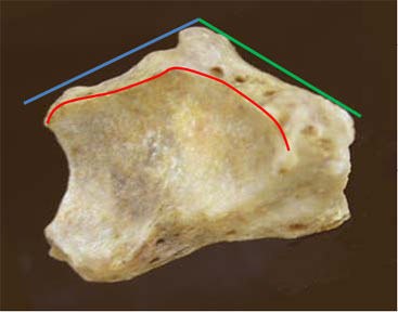
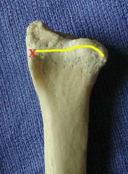
Plate placement can also effect the tendons. If the plate is placed too distally, the flare of the volar rim of the joint will cause the plate to be prominent along its distal margin. The plate should not extend beyond the watershed line (yellow line in Figure 17a), a term coined by Jorge Orbay that refers to the line at the highest (most volar) margin of the radius. This will be the part of the radius (or plate) that is closest to the flexor tendons and therefore at greatest risk of injuring them.
If the plate is placed too radially, a tuberosity called the volar radial tuberosity (see footnote 1), will raise up the radial margin. The tuberosity is easily palpated approximately 2 cm proximal to the volar tuberosity of the scaphoid (which is known to most surgeons in conjunction with the Watson test) and on the most radial aspect of the wrist. A plate placed too radially can become both clinically palpable (“Doc, is this bump supposed to be here? It wasn’t there before the surgery!”) and possibly a problem for the tendons, usually the flexor pollicis longus. If the plate is placed too ulnarly and has a flat profile across its distal margin, a bony feature called the lunate facet buttress (indicated by the red "x" in Figure 17b; see footnote 1) will raise up the ulnar margin. The lunate facet buttress is a bony area just proximal to the lunate facet. The lunate facet projects several millimeters volarly more than the scaphoid facet (Figure 5), and is supported by the lunate facet buttress, which varies in size from a millimeter to several millimeters. Some plates (Hand Innovations, Orthofix, and Acumed; see disclosure at the end of this article) are contoured to fit over the lunate facet buttress and still have the plate flat on the volar surface of the radius. The more distally a plate is placed and the larger the buttress is, the more relevant a contour in the plate becomes.
 |
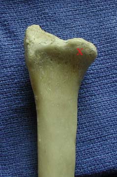 |
Figure 17a |
Figure 17b |
| Figure 17a is a volar view of a radius, with the lighting coming from the left to highlight the volar radial tuberosity (indicated by the red “x” in Figure 17a ) and, extending proximally, the volar radial ridge (see footnote 1) (see also Figure 44). The yellow line represents the watershed line. Figure 17b is the same specimen, with the lighting coming from the top to highlight the lunate facet buttress (indicated by the red “x”). | |
| Practical tip: Determining plate position is key: too distal, and you are into the joint; too proximal, and you do not support the subchondral bone; too radial, and the plate tilts on the volar radial tuberosity and may become palpable. Prior to placing a screw, do a trial placement with K-wires into one or more screw guides. Use fluoroscopy to determine where the screws will go, what fragments will be stabilized, and palpate the plate from skin to see if the plate is too radial. |
Clinical Example
31 YO male fell off a boat onto a dock and sustained a DRF. He had had a prior DRF at age 15, with some residual deformity. A locked volar plate that is well-contoured to fit a normal distal radius was placed in February of 2006. The volar surface of the radius was flatter than normal due to his prior fall, and since the plate was contoured to fit a normal radius, it did not fit well distally. The pronator quadratus was securely closed over the plate.
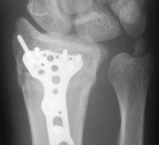
Figure 18
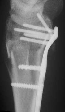
Figure 19
Postoperatively, at about 3-4 months, he complained of volar wrist pain with wrist extension and when he was carrying something very heavy. The patient developed paresthesias at 5 months. Surgical exploration was carried out at 7 months due to continuing symptoms.
 |
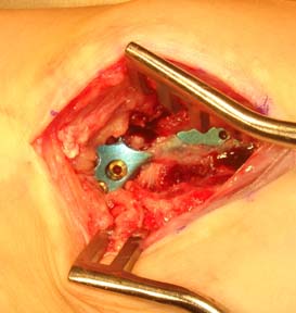 |
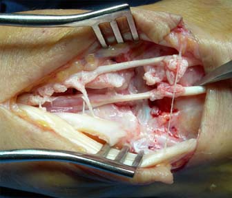
Figure 20a |
Figure 20b |
Damage was found to two tendons (Figure 20) but no rupture. There was a hole in the pronator quadratus and the plate was visible and felt to be prominent. The intraoperative assessment by the surgeon was that the properly pre-contoured plate did not fit the abnormal radius and that the screw holes felt “sharp” to his evaluation. The plate was removed and the symptoms resolved. (In addition, I have spoken to the manufacturer and confirmed that this was an early generation design. The design has undergone a number of improvements, such that there is less chance for screw hole “sharpness”. The author is not associated with this company or plate.)
Clinical Example
61 YO female bus driver fell in the schoolyard and sustained a volar Barton’s fracture in April of 2001 (Figures 21 and 22).
 |
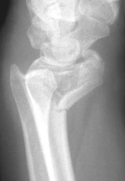 |
Figure 21 |
Figure 22 |
A volar Π plate (Pi plate; interestingly, this name was never used by Synthes, but was given to the plate by the community of users, due to the shape of the dorsal plate that was released at the same time and in the same set) was placed to buttress the fracture (Figure 23 and 24).
 |
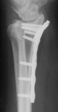 |
Figure 23 |
Figure 24 |
The fracture was incompletely reduced and the plate’s distal edge was therefore prominent. The patient developed a wrist ache with forceful use beyond 2 hours, which was attributed to her radioscaphoid arthritis. She developed subsidence of the scaphoid into the radius with cystic degeneration within a year (Figure 25), had an ache in her wrist, and retired as a bus driver.
Figure 25
In January of 2007, six years after surgery, she presented with the sudden onset of an inability to flex her thumb IP joint, wrist swelling and wrist tenderness. Xrays showed no progression of the subsidence of the scaphoid into the radius, resolution of the cystic degeneration, and that the plate continued to be prominent volarly.
 Figure 26 |
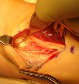
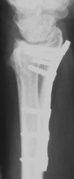 Figure 27 |
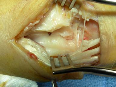
The diagnosis was made of a flexor pollicis longus rupture due to rubbing on the distal edge of the prominent plate. At surgery, the plate was found to be covered by a dense layer of scar tissue, except at one point. The most radial distal screw (there was one empty hole to the radial side of this screw) was easily seen through a rent in the scar tissue. The cruciate head of the screw was felt to be contributory.
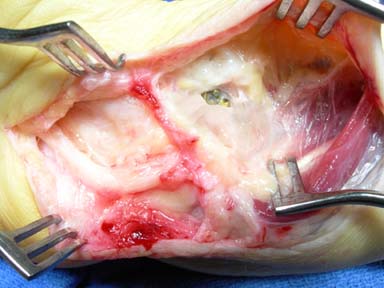
Figure 28
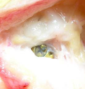
Figure 29
The tendon was grafted with a strip of flexor carpi radialis, as there was no palmaris longus. The bone had overgrowth the plate, but the titanium screws and plate were not firmly bonded to the bone and were removed without problem. She regained excellent range of motion of the thumb.
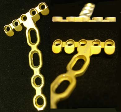
Figure 30
This is the plate removed from this case (Figure 30). It is a second-generation volar Π plate. The screw holes are surrounded by a raised lip that is high-profile and the distal margin of the plate has a sharply squared-off end. The screws had cruciate heads (see Figure 29). Cruciate heads can form razor-sharp edges if the screw driver slips out of the head while seating the screw. The current generation Synthes locked volar plates are much improved, and all have rounded edges, are lower profile, and use hex or torx screw heads.
There seems to be an advantage to covering the plate with the pronator quadratus (PQ) in order to interpose the muscle between the plate and the flexor tendons. During the initial dissection, most surgeons incise the PQ distally at the edge of the muscle fibers. This line is referred to as the PQ line (see footnote 1). After plate placement, most surgeons repair the PQ muscle. However, the thinness of the fascia of the muscle makes this an exercise in futility, as the sutures typically rip out before the next layer is closed. One technique that has proven to be quite secure is to release the PQ during the original dissection not along the margin of the muscular fibers (the PQ line), but 1-2 mm beyond the PQ line, into the fibrous tissue proximal to the volar capsule. This fibrous tissue, termed the fibrous transition zone (see footnote 1), has been determined in cadaveric dissections not to be part of the mobile volar wrist capsule (comprised of the radioscaphoid, radiocapitate, long radiolunate, and short radiolunate ligaments), but to be immobile and attached to the distal margin of the radius. It is felt that incising the fibrous transition zone should not add unnecessarily to wrist capsular scarring or wrist joint stiffness. Continue the dissection radially 1-2 mm into the fibrous tissue at the base of the first dorsal compartment. If this is done, there will be a 1-2 mm thick, strong margin along the edge of the PQ muscle. This margin will securely hold the sutures and the PQ will remain in place, serving as an interpositional layer between the plate and the flexor tendons.
| Practical tip: During the initial dissection, incise the PQ muscle 1-2 mm distal to the PQ Line. Continue the dissection radially 1-2 mm into the fibrous tissue at the base of the first dorsal compartment. This will create a strong 1-2 mm margin at the edge of the PQ muscle and allow a secure repair. |
![]()
(4) Subsidence of Fragments and/or Dorsal Subluxation of the Carpus due to Failure to Engage the Dorsal Ulnar Fragment
The dorsal ulnar corner of the radius cannot be neglected, due to the fact that it serves as the attachment point for the dorsal portion of the distal radioulnar joint (DRUJ) ligament. Forearm rotation exerts a very strong force on the dorsal ulnar fragment and can easily displace it. The dorsal ulnar fragment is usually not well visualized on either the PA or the lateral view, and oblique views are needed to assess it. Good screw purchase may be a challenge for such fragments with the volar approach. One should be prepared mentally for this challenge: either get good fixation with the most ulnar screw in the distal row or place a small dorsal, fragment-specific plate.
Clinical Example
A 20 YO male fell from a mountain bike and sustained bilateral wrist injuries. Xrays demonstrated bilateral DRF’s and a right scaphoid fracture. The left wrist is shown in Figures 30 and 31.
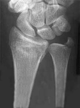 Figure 31 |
 Figure 32 |
The xrays indicated a fracture of the dorsal ulnar corner, so oblique views were obtained to assess its displacment (Figure 33).
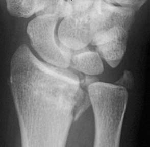
Figure 33
The oblique view much better demonstrated the size and displacement of the dorsal ulnar corner. The opposite wrist had a very similar DRF in addition to the scaphoid waist fracture. Open reduction and internal fixation was performed for all three fractures.
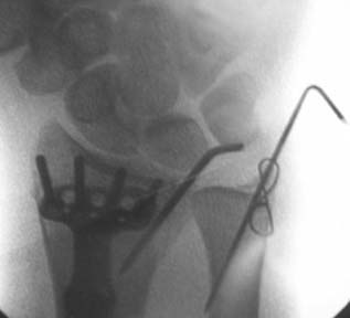
Figure 34
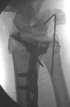 Figure 35 |
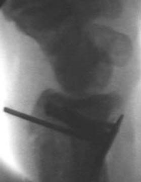 Figure 36 |
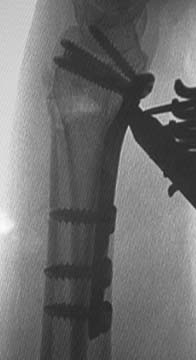
A locked volar plate was supplemented with a dorsal .062" K-wire to hold the left radius. Once the radius was fixed, DRUJ stability was assessed and found to be unstable. This was attributed to the ulnar styloid fracture. This was fixed with a .045" K-wire and figure-of-eight wire in a tension band configuration (Figures 34-36).
The patient was seen at one week and xrays obtained (Figures 37-39).
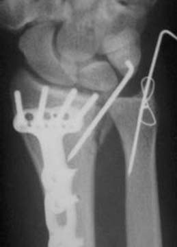
Figure 37
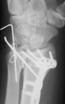 Figure 38 |
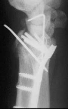 Figure 39 |
The follow-up views demonstrated displacement of the dorsal ulnar corner, in a manner identical to the original injury (Figures 36-38). A critical review of the immediate post-op films shows that the dorsal ulnar corner was not fixed with the volar plate and that the K-wire fixation was not stiff enough alone to resist the deforming forces. One could also speculate that the instability of the DRUJ was entirely or in part due to the dorsal ulnar corner rather than the ulnar styloid fracture. It was felt that the instability had a chance of progressive subsidence, and further fixation was required. (The opposite wrist had an identical subsidence and was also re-operated.)
 |
 |
 |
Figure 40 |
Figure 41 |
Figure 42 |
The patient was returned to the operating room where a dorsal plate was placed through a dorsal incision (Figures 40-42). This reduction was maintained and at one year the patient had good motion with little to no pain.
| Practical tip: If there is a dorsal ulnar fragment you need to stabilize, determine the future axis of the ulnar-most screw by placing a K-wire though the drill guide locked into the ulnar screw hole in the plate. Leave the K-wire in place, remove the guide and plate. Obtain a fluoroscopic view of the K-wire end-on. This view will determine precisely if the screw will be in the fragment. The patient was returned to the operating room where a dorsal plate was placed through a dorsal incision (Figures 39-41). This reduction was maintained and at one year the patient had good motion with little to no pain. |
![]()
(5) Subsidence of Fragments and Volar Subluxation of the Carpus due to Failure to Stabilize the Volar Rim of the Lunate Facet
Small volar rim fragments are difficult to stabilize and experience has shown that they are easily underestimated. Common mistakes are to place the plate too radially, too proximally, or to choose a technique or plate that cannot stabilize the volar rim of the lunate.
 |
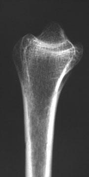 |
Figure 43 |
Figure 44 |
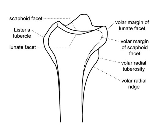
Figure 45
Figure 42 is the lateral view of a dried radius from the ulnar side, and Figure 43 is an xray of that specimen in approximately the same projection (the scaphoid and lunate facets are overlapping in the dried radius but offset in the xray). Figure 44 identifies several anatomic features. The key point is that the lunate facet projects quite a bit volarly (see also Figure 2), and that the center of the facet is directly over the volar aspect of the radius. It is not over the center of the medullary canal. The load from the carpus places a force on the lunate facet that has a component that is distinctly volarly-directed. This, combined with the extent of volar projection of the lunate facet, makes lunate rim fractures very unstable.
No locked volar plate extends to the volar lip of the lunate facet. The one that comes the closest is the Synthes 2.4 LCP Volar Juxta-Articular Distal Radius Plate. Most designs do not want to extend that far past the watershed line and risk injuring the flexor tendons, and how far a plate should extend distally is controversial. However, in the case of a fracture of the volar lip of the lunate facet, some kind of stabilization is required, and some violation of the watershed line is needed. Various techniques have been used or proposed, including using the Synthes Juxta-Articular plate, placing a standard plate more distally, using a fragment-specific approach, or K-wires. The effectiveness of each approach depends on the fragment size, the technique used, and the actual shape of the implant. The Synthes Juxta-Articular plate or the fragment specific approaches are probably the most common, but each have their limitations. The Synthes plate unnecessarily extends beyond the watershed line for the scaphoid facet, which does not need support. The fragment specific approach is less stable and more complex to apply.
Clinical Example
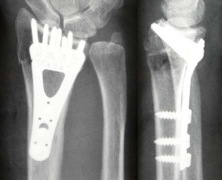
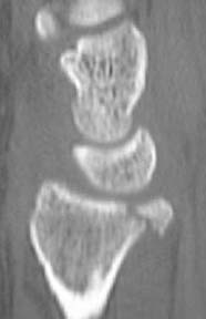
A19 YO male fell sustaining a DRF. Xrays showed a very distal volar lip fracture of the radius and slightly rotated radial styloid fracture, with just enough volar subluxation of the lunate to suggest volar instability (Figures 46 and 47).
 |
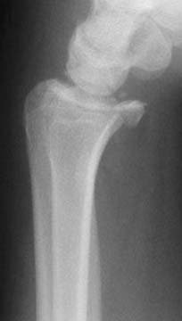 |
Figure 46 |
Figure 47 |
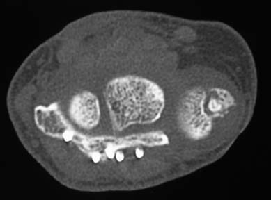
A CT scan (Figure 48) and CT reconstruction with the carpus removed (Figure 49) confirmed the size, shape, and location of the fragments, as well as the volar subluxation of the lunate.
 |
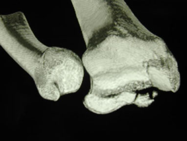 |
Figure 48 |
Figure 49 |
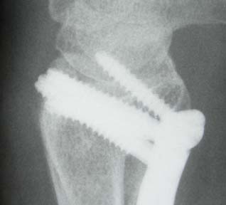
It was felt that a standard locked plate would not stabilize this fracture, and a fragment-specific technique was used (Figures 50 and 51).
 |
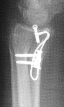 |
Figure 50 |
Figure 51 |
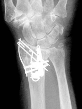
Another clinical case, with a more complex fracture, was stabilized with a similar technique.
 |
 |
Figure 52 |
Figure 53 |
![]()
(6) Placement of the Distal Screws too Proximally and Failing to Support the Subchondral Bone
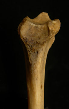
Older patients with severe osteoporosis are a challenge to treat. Locked volar plates take advantage of the two strongest areas of bone, which are the volar cortex just proximal to the metaphyseal bone and the subchondral bone. Figure 43 is an xray of an osteoporotic bone in the author’s collection. The bone is quite fragile. However, the xray clearly demonstrates that these two areas are the most dense, with little bone showing in the dorsal cortex of the metaphyseal bone or a few mm proximal to the subchondral bone. While distal screws can support the joint several mm away from the subhcondral bone in younger patients, they need to be placed distally in the osteoporotic patient. If the screws are several millimeters away from the subchondral bone, they may settle thorough the cancellous metaphyseal bone until they reach the subchondral bone. The author is not aware of any case in which the distal screws have settled through the subchondral bone.
![]()
(7) Prominent Hardware that is Clinically Palpable Volarly due to Implant Placement too far Radially
Palpate the volar radial tuberosity (Figure 44) in your own wrist. It is 2 cm proximal to the volar tuberosity of the scaphoid (the part of the scaphoid where you push for the Watson test), at the most radial border of the wrist. It is quite subcutaneous, with little overlying fat. Plates that are placed too radially can be easily palpated by the patient. Care must be taken, prior to the drilling for the first screw, to assess the plate placement. Most plate systems have methods to hold the plate in place while the placement is assessed radiographically, either K-wire holes or drill guides that accept K-wires. Once the position of the plate is tentatively determined, remove the retractors, replace the skin edges, and palpate the skin over the volar radial tuberosity. Move the plate if required.
![]()
(8) Inability to Remove a Plate/Screws due to Bony Adherence to Titanium Implants
There have been reports of titanium screws being so firmly bonded to the bone that the heads shear off, the driver tip shears off, or the head strips out. The surgeons have had to resort to breaking the implants and burring off any projecting screw remnants. This point remains controversial. Some authors recommend the use of stainless steel implants to avoid bonding and screw breakage, and others claim that there is no chemical bonding between bone and titanium. It is interesting to observe the competing claims of two groups with very different agendas: the trauma companies deny that bonding to their titanium implants exists, while at the same time the total joint companies tout the strength of the bonding to their titanium implants. Many surface treatments, from polishing to chemical treatment or hydroxyapetite coating, have been tried to avoid or enchance bonding. The controversy does not seem to have a resolution at this time, and there does not seem to be a clear reason to avoid titanium locked volar plates. In the one case of late titanium plate removal in the author’s experience, at six years after implantation (case cited above, involving a second-generation Synthes titanium plate, Figures 28-30), all screws were easily removed, once the bony overgrowth covering the screw heads was removed.
![]()
(9) Tendonitis due to Titanium
Tendonitis due to titanium is even more controversial than the inability to remove titanium screws due to bonding. Some authors of animal studies report finding titantium synovitis that is more than found with stainless steel, while others report the opposite. The influence of synovial fluid on the formation of tendonitis is also controversial. My personal experience, with volar titanium plates in for from one to six years, is that I have not seen synovitis. At this time, there does not seem to be a clear reason to avoid titanium locked volar plates.
![]()
End Notes
Here are some suggestions to avoid complication and to improve your results:
(1) Nothing is so humbling as reviewing your own cases two or so years later. Be brutal in your criticisms.
(2) Perform a cadaveric dissection. When you know you don’t have to repair anything and the exposure can be exceedingly wide, a lot of new lessons will be learned. Our normal exposure windows hide as much as they reveal.
(3) Obtain and study a distal radius. You can’t reconstruct a bone if all you look at are shadows (xrays) and microviews (surgical exposures). I have kept one on my desk for 14 years (seen in Figures 4, 5, and 42), and this one bone has taught me a treasure-trove of lessons.
![]()
Footnote 1 These terms have been proposed by David Nelson, Jorge Orbay, and Randi Bindra, in an article in submission to the Journal of Hand Surgery, American. See this article on eRadius.
Disclosure: the author has designed a locked volar plate and receives royalties related to that plate.
The author would like to acknowledge the contribution of Drs. Jorge Orbay and Randi Bindra for the development of the new anatomic terms, and Drs. Kendrick Lee, Stefan Zachary, Michael Grafe, and Rob Medoff for the contribution of clinical material. The author is actively solicting the submission of complications, so that they can be collated, analyzed, and disseminated to the surgical community. Contact the author at
![]()
| About Us | Research | Basic Knowledge | What's New | Forum | Guest Professor | Post a Case | eRadius Conference | Patients | Home |